


본문
Í≥ÝÏÝÑÏïïÏö© Ϫ§ÎÑ•ÌÑ∞
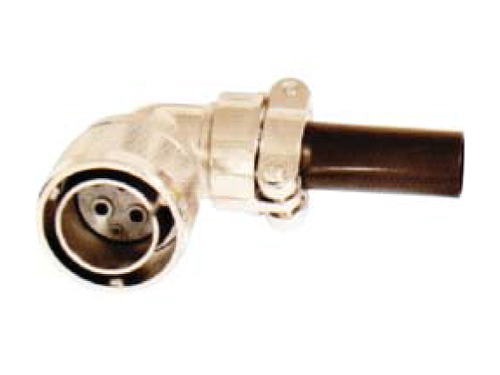
Ïù¥ Ϫ§ÎÑ•ÌÑ∞Îäî VG95234 Í∏∞ϧÄÏùÑ Îî∞Ε¥Í≥Ý ÏûàÍ≥Ý YH-BayonetÏôÄ Í∞ôÏùÄ Ïãúζ¨Ï¶àÏûÖÎãàÎã§. Ïù¥ Ϫ§ÎÑ•ÌÑ∞Îäî YH 5015 StyleÏùò ÏÝúÌíàÏùÑ Í∏∞Ï°¥ ÎÇòÏǨ ÌÉÄÏûÖÏùò Í≤∞Ìï©Î∞©ÏãùÏóêÏÑú Bayonet Í≤∞Ìï© Î∞©ÏãùÏúºÎ°ú Ìñ•ÏÉÅÏãúÌÇ® Ι®Îç∏ÏûÖÎãàÎã§. ÌäπÌûà Ïù¥ ÏÝúÌíàÏùÄ ÏßÑÎèôÏóê ÏùòÌïú Í∏∞Ï≤¥Ïùò ÏúÝÎèôÏ≤¥ Î≥¥Ìò∏Εº ÏúÑÌï¥ Í≥ÝÏïàÎêòÏóàÏúºÎ©∞ Í≤∞Ìï©Í≥º Î∂Ñζ¨Î•º ÏâΩÍ≤å ÌïÝ Ïàò ÏûàÎäî Ïû•ÏÝêÏù¥ ÏûàÏäµÎãàÎã§. Ïù¥ ÏÝúÌíàÏùÄ Ï£ºÎ°ú Î∞©ÏÇ∞Ïö© Ï∞®ÎüâÍ≥º ÏÝÑÍ∏∞ÏûêÎèôÏ∞®, ÏÑÝÎ∞ïÏö© Ïû•ÎπÑ, ÌܵÏãÝÏû•ÎπÑÏóê ÏǨÏö©Îê©ÎãàÎã§.
Ordering Information

- RoHS
-
BLANK - Non RoHS
Y/ - RoHS - YH Number Shell Style
-
YH00V - Wall Mounting Receptacle
YH01V - Cable Connecting Plug
YH02V - Box Mounting Receptacle
YH06V - Straigt Plug
YH08V - 90’Angle Plug - Class
-
A - Solid shell for general, non-environmental applications
E - With resilient insulator and integral clamp for cable strain relief
F - Same as E, However style 06 with O-ring seal under the coupling nut
R - With resilient insulator and shortened, lightweight endbell
(additional sealing with O-ring under the coupling nut for shell styles 06 and 08) - Shell Size
-
10SL,12S,12,14S,16S,16,18,20,22,24,28,32,36
- Contact Style
-
P - Solder Pin(Male)CP - Crimp Pin(Male)
S - Solder Socket(Female)CS - Crimp Socket(Female) - Alternate Insert Position
-
N(Nomal),W,X,Y,Z (MIL-STD-1651)
- Finish
-
Blank - Conductive Olive Drab Chromate Over Zinc Plate
A - Black Zinc Cobalt Plate
N - Nikel Plate - Pin Pole
-
1 Pole ~ 73 Pole
Electrical Data
| Contact Arrangements Service Rating | |||||||
|---|---|---|---|---|---|---|---|
| Dielectric Withstanding Voltage | Contact Engaging & Separating Force | ||||||
| Service Rating | Test Voltage AC(rms) |
Operating Voltage | Contact Size | Force in Lab | |||
| AC(rms) | DC | Maximum | Average | Minimum | |||
| Inst. | 1,000 | 200 | 250 | 16 | 3.00 | 2.06 | 0.13 |
| a | 2,000 | 500 | 700 | 12 | 5.00 | 3.5 | 0.19 |
| b | 2,800 | 900 | 1,250 | 8 | 10.00 | 0.31 | |
| c | 3,500 | 1,250 | 1,750 | 4 | 15,00 | 0.63 | |
| d | 4,500 | 1,750 | 2,450 | 0 | 20.00 | 0.94 | |
| e | 7,000 | 3,000 | 4,200 | ||||
| Contact Size | Pin Contact Dia. |
Solder Pot Dia. |
Current(A) Rating (Mated With Insulators |
Contact Resistance | Wire Range Accommodations | |||
|---|---|---|---|---|---|---|---|---|
| Test Current (A) |
Potential Drop Max(mV) |
Wire Size (AWG) |
Wire Nomal Square Size(„éü) |
Dielectric Material Outer Dia. |
||||
| 16 | 1.6 | 2.0 | 13 A | 20 A | 21 | 16~22 | ≤ 1.3 | 1.7~3.3 |
| 12 | 2.4 | 3.0 | 23 A | 35 A | 20 |
12~14 |
≤ 3.5 | 2.9~4.3 |
| 8 | 3.6 | 5.2 | 46 A | 60 A | 12 | 8~10 | ≤ 8.0 | 4.2~6.4 |
| 4 | 5.7 | 8.5 | 80 A | 110 A | 10 | 6~4 | ≤ 22.0 | 7.0~9.4 |
| 0 | 9.2 | 12.0 | 150 A | 200 A | 10 | 0~2 | ≤ 50.0 | 10.6~14.0 |
| Operating Temperature Range | -55 ‚ÑÉ ~ 125 ‚ÑÉ |
|---|---|
| Insulation Resistance | 5 000 ㏁ Min.(at 25 ℃) |
| Durability | 500 cycle,mate and unmate |