


Š°¡Š˜¡
YH 95234
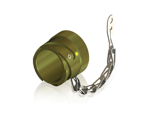
VG95234 õñõýˋõ°¥ š¥š¿ÚŠ, YH-Bayonet šŠÎ˜šÎ š£ÊŠËÚ¯ š ŠŠÊ. šÇ š£ÊŠËÚ¯Š 5015š Šš˜š õý¯ÚˋŠ¯ˋšš bayonet Š¯ˋšš¥ŠÀ õ¯ŠÚš˜ õý¯Úˋ/ŠÑŠÎ˜õ¯ š§ŠŠÀ š šŠ š£ÊŠËÚ¯ š ŠŠÊ. šÏŠš šÚ š šýÇ š¿´Ú˜ŠÀŠÑÚ¯ Š°ÇÚ¡ŠË¥ Šˆˋš š¥ŠÀ ÚŠ õ°°š š˜šˋÚŠŠ¯ š ÚˋÚŠŠÀ šÊõ°Š š ښNJˋ¯, õý¯Úˋ/ŠÑŠÎ˜õ¯ š§ŠŠÀ šÊõ° ŠššçŠŠÊ. ÚÙõ°çõ¡¯ Š¯ õ篚ˋ š¯´Š, š š¯´, Š¯¯ŠÝš šËŠ¿ Š¯ š Š°ÇÚçš šËŠ¿ ŠÝš š˜šˋŠõ° ššçŠŠÊ.
šÈ¥Š˜¡ š Š°Ç (Ordering Information)
VG Nomenclature
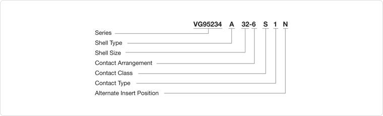
- Series VG95234
- Shell Style
-
J1, J2, N1, N2, S1, U1, U2 - Wall Mounting Receptacle
F - Cable Connection Plug
A, B1, B2 - Box Mounting Receptacle
C1, C2 - Bulkhead Receptacle
D, G, H, L, M, R1 - Straight Plug
E, E1, K - Plug 90ô¯ - Shell Size
- 10SL, 14S, 16S, 16, 18, 20, 22, 24, 28, 32, 36
- Contact Arrangement
-
Refer to VG95234 specification
- Contact Style
-
P - Pin Contact
S - Socket Contact - Contact Type
-
Letter 1 indicates the electrical wire size.
- Alternate Insert Position
-
Refer to VG95234 specification.
- VG Accessories
-
VG95234 BOD - Dummy Receptacle
VG95234 DA - Gaskets, Front Mount
VG95234 DH - Gaskets, Rear Mount
VG95234 KR - Protecting Caps
VG95234 KB - Protecting Caps
VG95234 KK - Cable Caps
VG95234 KT - Bushing
YEONHAB Nomenclature
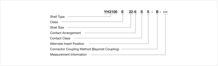
- Shell type
-
YH3100 - Wall Mounting Receptacle
YH3101 - Cable Connection Plug
YH3102 - Box Mounting Receptacle
YH3106 - Plug, Straight
YTBF - Bulkhead Receptacle - Environmental rating
-
E - appropriately uses clamp and bushings in flexible rubber insulator and end bell.
- Shell Size
- 10SL, 14S, 16S, 16, 18, 20, 22, 24, 28, 32, 36
- Contact Arrangement
-
Refer to the VG95234 specification and MIL-STD-1651.
- Contact Style
-
P - Pin Contact
S - Socket Contact - Alternate Insert Position
-
Refer to the VG95234 specification and MIL-STD-1651.
- Connector Coupling Method
-
Bayonet Coupling
- Measurement Information
-
01-Metric clamping contact
02-Uses heat shrink boots in adaptor. AWG clamping contact
03-Uses heat shrink boots in adaptor. Metric clamping contact
04-Rear Mount. Screw-type hole flange. Metric clamping contact
05-Rear Mount. Screw-type hole flange. Soldering type contact (YH3100, YH3102, YTBF applied) 06-Heat shrink boot adaptor. Screw-type hole flange. Soldering type contact
08-90ô¯ end bell. Screw-type hole flange (YH3100 applied)
09-90ô¯ end bell. Through-hole flange (YH3100 applied)
13 - shield version. Soldering type contact
14 - shied version. Metric clamping contact.
15 - shield version. AWG clamping contact.
32 - end bell structure for shield system cable. MTV6145-005.
109-F80. Rear Amount. Screw-type flange(YH3102 applied)
111-Rear amount. screw-type flange(YH3102 applied). Soldering type contact.
F80-AWG clamping contact.
A232 - Zinc cobalt plating(black)
YEONHAB Nomenclature
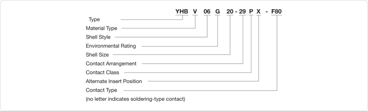
- Product Type
-
YHB-General connector
YHBG-EMI Ground Finger type connector - Material Type
-
Blank - Standard(CR) insulator
V - Silicon(SR) insulator - Shell Size
-
01 - In-Line Receptacle
02/00 - Front Panel Mount Receptacle
03/030 - Rear Panel Mount Receptacle
06 - Straight Plug
07 - Single Hole Mount Jamnut Receptacle, No Rear Thread
070 - Single Hole Mount Jamnut Receptacle, With Rear Thread
08 - 90ô¯Plug - Shell Size
-
10SL, 14S, 16S, 16, 18, 20, 22, 24, 28, 32, 36
- Contact Arrangement
-
Refer to the VG95234 specification and MIL-STD-1651.
- Alternate Insert Position
-
Refer to the VG95234 specification and MIL-STD-1651.
- Contact Type
-
F80-AWG clamping contact
CR-Metric clamping contact
Blank - soldering contact - Environmental Rating
-
It is based on the accessories and backshell that seal according to each rating.
G - heat shrink boots are used for end bell accessories. includes grommet and bushing. (applicable to 01,00,030, 06)
AG - excludes grommet and bushing from G rating
R - other accessories are used for end bell accessories. includes grommet and bushing. (08-90 end bell)
SB - EMI blade and heat shrink boots used. includes grommet and bushing.
SBT - EMI blade, heat shrink ring and heat shrink boots used. includes grommet and bushing.
F - includes cable clamp and rubber bushing.
AF- excludes grommet and bushing from F rating
FP - the panel mounting hole is a through-hole type
RG - EMI coil ground finger tyle (applicable to 07, 070)
- Contact class
-
P - Pin Contact
S - Socket Contact
õ¡¯š š š Š°Ç (Technical Data)
Electrical Information
Electrical Information (20 ã)| Contact Rating | Max. Current | |
|---|---|---|
| Metric | AWG | A |
| 10 | - | 8 |
| 15/15S | 16/16S | 22 |
| 25 | 12 | 41 |
| 60/100 | 8 | 74 |
| 160 | 4 | 135 |
| 500 | 0 | 245 |
Contact Resistance
VG95319 Part 2š šÚŠýÚ¡ 5.12š VG95210 Part 32š šÚšÀ¯õÝÇ Bš š¥š¿Ú õý.ÚšÊ(CR) š š¯šýÇ > 1 000 Möˋ
šÊŠÎ˜š§(SR) š š¯šýÇ > 5 000 Möˋ
Required to meet the testing no. 5.12 in Part 2 of VG95319
and testing condition B in Part 32 of VG95210.
Standard(CR) insulator > 1 000 Möˋ
Silicon(SR) insulator > 5 000 Möˋ
Contact Resistance (Milivolt testing)
| Voltage testing per service rating | |
|---|---|
| Service Rating | Testing Voltage (V rms) |
| Instruments | 1 050 |
| A | 1 600 |
| B | 4 000 |
| D | 2 500 |
| E | 3 000 |
Air and Creepage Paths(Min.) (UNIT: mm)
| Voltage Rating | Instr. | A | D | E |
|---|---|---|---|---|
| Air and Creepage Paths | 0.70 | 1.10 | 2.80 | 4.80 |
Current Rating (according to ambient temperature)
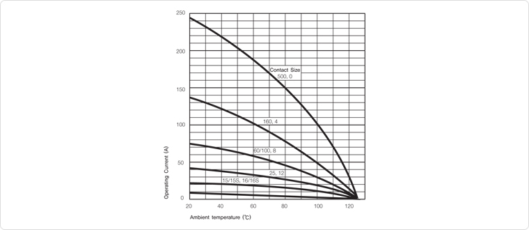
of VG95234 and Part 37 of VG95210.
It represents the actually measured point.
| Contact Rating | Max. Current | |
|---|---|---|
| Metric | AWG | Möˋ |
| 10 | - | 12 |
| 15S/15 | 16/16S | 6 |
| 25 | 12 | 3 |
| 60/100 | 8 | 1 |
| 160 | 4 | 0.5 |
| 500 | 0 | 0.2 |
Mechanical characteristics
Ambient temperature| Material | Temperature range |
|---|---|
| Standard(CR) insulator | -55 ã ~ 125 ã |
| Silicon(SR) insulator | -30 ã ~ 200 ã |
| Vibration testing | 200 дšš 10 Ð ~ 2 000 Ð |
| Coupling testing | Min. 500 times |
Contact Separating Force
| Contact Size | Separating Force(Min) | ||
|---|---|---|---|
| Metric | AWG | N | Gauge |
| 10 | - | 0.30 | G 0.99 |
| 15S/15 | 16S/16 | 1.00 | G 1.56 |
| 25 | 12 | 1.50 | G 2.36 |
| 60/100 | 8 | 3.00 | G 3.58 |
| 160 | 4 | 4.00 | G 5.69 |
| 500 | 0 | 8.50 | G 9.04 |
Gauge (VG95234, Part 1)
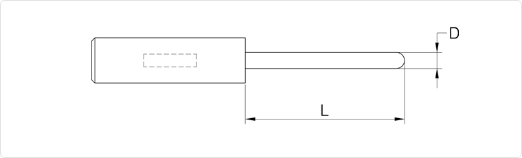
| Gauge | D +0.01 -0.00 |
L +0.00 -1.00 |
|---|---|---|
| G 0.99 | 0.99 | 7.00 |
| G 1.56 | 1.56 | 9.00 |
| G 2.36 | 2.36 | 12.00 |
| G 3.58 | 3.58 | 13.00 |
| G 5.69 | 5.69 | 13.00 |
| G 9.04 | 9.04 | 13.00 |
Coupling Torque
| Shell Size | Approved Coupling Torque | |
|---|---|---|
| Locking and unlocking Nm Max. |
unlocking Nm Min |
|
| 10SL | 1.70 | 0.15 |
| 14S | 3.60 | 0.35 |
| 16S/16 | 5.50 | 0.46 |
| 18 | 8.00 | 0.58 |
| 20 | 9.00 | 0.70 |
| 22 | 11.00 | 0.80 |
| 24 | 14.00 | 0.80 |
| 28 | 17.00 | 0.92 |
| 32 | 19.00 | 1.03 |
| 36 | 23.00 | 1.03 |
Contact Retention Force
| Contact Size | Testing power | |
|---|---|---|
| Metric | AWG | N |
| 10 | - | 30 |
| 15S/15 | 16S/16 | 35 |
| 25 | 12 | 55 |
| 60/100 | 8 | 80 |
| 160 | 4 | 90 |
| 500 | 0 | 95 |
Testing power direction = locking direction.
Material and protection coating
| Body | aluminum alloy |
|---|---|
| Standard protection coating | cadmium plating(viridescent color) on top |
| Substitute protection coating | Zinc cobalt plating(black) |
| Insulator and grommet | Chloroprene Rubber(standard) Slicone Rubber(for high temperature) |
| Contact | Copper alloy |
| Protection coating | Hard silver plating |
š š¯šýÇ (Insulator)

| NBR(Nitrile Butadiene Rubber) | CR(Chloprene Rubber) | |
|---|---|---|
| šËš | ŠÇš šÝšÇ š¯šÚ´(õý§š , ÚŠ¯š ) | ŠÇÚšÝ,ŠÇš§ÚšÝ,ŠÇš šÝ,Šš¯šÝ, šÊšÀÇšÝ, ŠÇšÇšÝ, Š ¡ÚšÝšÇ š¯šÚ´ |
| ŠÇŠÏŠˆ´šÝ,ŠÇššÝ, ŠÇŠ ¡ÚšÝšÇ š¯šÚ´ | õ¯šÊ Ú˜õ°¥šÝšÇ š š | |
| š š¯ˋŠ ËšÇ š¯šÚ´ | ||
| õçÇõ°ÀښǚÝ,ŠÇŠÏŠˆ´šÝšÇ š¯šÚ´ | ||
| ŠÇšÇšÝ 150 ãõ¿šÏ š˜šˋ õ¯ŠËÚ´ | ||
| õ¯õýˋ | ŠÛš | Šš |